- 您现在的位置:买卖IC网 > Sheet目录329 > IDT71342LA25PFI (IDT, Integrated Device Technology Inc)IC SRAM 32KBIT 25NS 64TQFP
IDT71342SA/LA
High-Speed 4K x 8 Dual-Port Static RAM with Semaphore
Industrial and Commercial Temperature Ranges
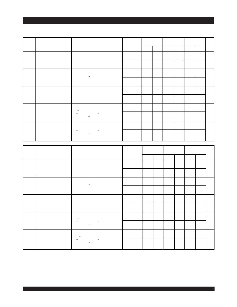
DC Electrical Characteristics Over the Operating
Temperature and Supply Voltage Range (1) (V CC = 5.0V ± 10%)
71342X20
Com'l Only
71342X25
Com'l & Ind
71342X35
Com'l Only
Symbol
Parameter
Test Condition
Version
Typ. (2)
Max.
Typ. (2)
Max.
Typ. (2)
Max.
Unit
I CC
I SB1
I SB2
I SB3
I SB4
Dynamic Operating Current
(Both Ports Active)
Standby Current
(Both Ports - TTL
Level Inputs)
Standby Current
(One Port - TTL
Level Inputs)
Full Standby Current (Both
Ports -
CMOS Level Inputs)
Full Standby Current
(One Port -
CMOS Level Inputs)
CE = V IL ,
Outputs Disabled
SEM = Don't Care
f = f MAX (3)
CE L and CE R = V IH
SEM L = SEM R > V IH
f = f MAX (3)
CE "A" = V IL and CE "B" = V IH
Active Port Outputs Disabled,
f=f MAX (3)
Both Ports CE L and
CE R > V CC - 0.2V,
V IN > V CC - 0.2V or V IN < 0.2V
SEM L = SEM R > V CC - 0.2V
f = 0 (3)
One Port CE "A" or
CE "B" > V CC - 0.2V
V IN > V CC - 0.2V or V IN < 0.2V
SEM L = SEM R > V CC - 0.2V
Active Port Outputs Disabled,
f = f MAX (3)
COM'L
IND
COM'L
IND
COM'L
IND
COM'L
IND
COM'L
IND
SA
LA
SA
LA
SA
LA
SA
LA
SA
LA
SA
LA
SA
LA
SA
LA
SA
LA
SA
LA
170
170
____
____
25
25
____
____
105
105
____
____
1.0
0.2
____
____
105
105
____
____
280
240
____
____
80
80
____
____
180
150
____
____
15
4.5
____
____
170
130
____
____
160
160
160
160
25
25
25
25
95
95
95
95
1.0
0.2
1.0
0.2
95
95
95
95
280
240
310
260
80
50
100
80
180
150
210
170
15
4.0
30
10
170
120
210
190
150
150
150
150
25
25
25
25
85
85
85
85
1.0
0.2
1.0
0.2
85
85
85
85
260
200
300
250
75
45
75
55
170
140
200
160
15
4.0
30
10
150
110
190
130
mA
mA
mA
mA
mA
2721 tbl 06a
71342X45
Com'l Only
71342X55
Com'l Only
71342X70
Com'l Only
Symbol
Parameter
Test Condition
Version
Typ. (2)
Max.
Typ. (2)
Max.
Typ. (2)
Max.
Unit
I CC
I SB1
I SB2
I SB3
I SB4
Dynamic Operating Current
(Both Ports Active)
Standby Current
(Both Ports - TTL
Level Inputs)
Standby Current
(One Port - TTL
Level Inputs)
Full Standby Current (Both
Ports -
CMOS Level Inputs)
Full Standby Current
(One Port -
CMOS Level Inputs)
CE = V IL ,
Outputs Disabled
SEM = Don't Care
f = f MAX (3)
CE L and CE R = V IH
SEM L = SEM R > V IH
f = f MAX (3)
CE "A" = V IL and CE "B" = V IH
Active Port Outputs Disabled,
f=f MAX (3)
Both Ports CE L and
CE R > V CC - 0.2V,
V IN > V CC - 0.2V or V IN < 0.2V
SEM L = SEM R > V CC - 0.2 V
f = 0 (3)
One Port CE "A" or
CE "B" > V CC - 0.2V
V IN > V CC - 0.2V or V IN < 0.2V
SEM L = SEM R > V CC - 0.2V
Active Port Outputs Disabled,
f = f MAX (3)
COM'L
IND
COM'L
IND
COM'L
IND
COM'L
IND
COM'L
IND
SA
LA
SA
LA
SA
LA
SA
LA
SA
LA
SA
LA
SA
LA
SA
LA
SA
LA
SA
LA
140
140
____
____
25
25
____
____
75
75
____
____
1.0
0.2
____
____
75
75
____
____
240
200
____
____
70
40
____
____
160
130
____
____
15
4.0
____
____
150
100
____
____
140
140
140
140
25
25
25
25
75
75
75
75
1.0
0.2
1.0
2.0
75
75
75
75
240
200
270
220
70
40
70
50
160
130
180
150
15
4.0
30
10
150
100
170
120
140
140
____
____
25
25
____
____
75
75
____
____
1.0
0.2
____
____
75
75
____
____
240
200
____
____
70
40
____
____
160
130
____
____
15
4.0
____
____
150
100
____
____
mA
mA
mA
mA
mA
NOTES:
2721 tbl 06b
1. 'X' in part number indicates power rating (SA or LA).
2. V CC = 5V, T A = +25°C for typical, and parameters are not production tested.
3. f MAX = 1/t RC = All inputs cycling at f = 1/t RC (except Output Enable). f = 0 means no address or control lines change. Applies only to inputs at CMOS level standby I SB3.
6.42
发布紧急采购,3分钟左右您将得到回复。
相关PDF资料
IDT7134LA25JI
IC SRAM 32KBIT 25NS 52PLCC
IDT7140LA55C
IC SRAM 8KBIT 55NS 48DIP
IDT7142LA55C
IC SRAM 16KBIT 55NS 48DIP
IDT7143LA25G
IC SRAM 32KBIT 25NS 68PGA
IDT7164L25YGI
IC SRAM 64KBIT 25NS 28SOJ
IDT71T75802S200PFGI
IC SRAM 18MBIT 200MHZ 100TQFP
IDT71T75902S85BGG
IC SRAM 18MBIT 85NS 119BGA
IDT71V016SA12PHGI
IC SRAM 1MBIT 12NS 44TSOP
相关代理商/技术参数
IDT71342LA25PFI8
功能描述:IC SRAM 32KBIT 25NS 64TQFP RoHS:否 类别:集成电路 (IC) >> 存储器 系列:- 标准包装:72 系列:- 格式 - 存储器:RAM 存储器类型:SRAM - 同步 存储容量:9M(256K x 36) 速度:75ns 接口:并联 电源电压:3.135 V ~ 3.465 V 工作温度:-40°C ~ 85°C 封装/外壳:100-LQFP 供应商设备封装:100-TQFP(14x14) 包装:托盘 其它名称:71V67703S75PFGI
IDT71342LA35J
功能描述:IC SRAM 32KBIT 35NS 52PLCC RoHS:否 类别:集成电路 (IC) >> 存储器 系列:- 标准包装:72 系列:- 格式 - 存储器:RAM 存储器类型:SRAM - 同步 存储容量:9M(256K x 36) 速度:75ns 接口:并联 电源电压:3.135 V ~ 3.465 V 工作温度:-40°C ~ 85°C 封装/外壳:100-LQFP 供应商设备封装:100-TQFP(14x14) 包装:托盘 其它名称:71V67703S75PFGI
IDT71342LA35J8
功能描述:IC SRAM 32KBIT 35NS 52PLCC RoHS:否 类别:集成电路 (IC) >> 存储器 系列:- 标准包装:72 系列:- 格式 - 存储器:RAM 存储器类型:SRAM - 同步 存储容量:9M(256K x 36) 速度:75ns 接口:并联 电源电压:3.135 V ~ 3.465 V 工作温度:-40°C ~ 85°C 封装/外壳:100-LQFP 供应商设备封装:100-TQFP(14x14) 包装:托盘 其它名称:71V67703S75PFGI
IDT71342LA35PF
功能描述:IC SRAM 32KBIT 35NS 64TQFP RoHS:否 类别:集成电路 (IC) >> 存储器 系列:- 标准包装:72 系列:- 格式 - 存储器:RAM 存储器类型:SRAM - 同步 存储容量:9M(256K x 36) 速度:75ns 接口:并联 电源电压:3.135 V ~ 3.465 V 工作温度:-40°C ~ 85°C 封装/外壳:100-LQFP 供应商设备封装:100-TQFP(14x14) 包装:托盘 其它名称:71V67703S75PFGI
IDT71342LA35PF8
功能描述:IC SRAM 32KBIT 35NS 64TQFP RoHS:否 类别:集成电路 (IC) >> 存储器 系列:- 标准包装:72 系列:- 格式 - 存储器:RAM 存储器类型:SRAM - 同步 存储容量:9M(256K x 36) 速度:75ns 接口:并联 电源电压:3.135 V ~ 3.465 V 工作温度:-40°C ~ 85°C 封装/外壳:100-LQFP 供应商设备封装:100-TQFP(14x14) 包装:托盘 其它名称:71V67703S75PFGI
IDT71342LA45J
功能描述:IC SRAM 32KBIT 45NS 52PLCC RoHS:否 类别:集成电路 (IC) >> 存储器 系列:- 标准包装:72 系列:- 格式 - 存储器:RAM 存储器类型:SRAM - 同步 存储容量:9M(256K x 36) 速度:75ns 接口:并联 电源电压:3.135 V ~ 3.465 V 工作温度:-40°C ~ 85°C 封装/外壳:100-LQFP 供应商设备封装:100-TQFP(14x14) 包装:托盘 其它名称:71V67703S75PFGI
IDT71342LA45J8
功能描述:IC SRAM 32KBIT 45NS 52PLCC RoHS:否 类别:集成电路 (IC) >> 存储器 系列:- 标准包装:72 系列:- 格式 - 存储器:RAM 存储器类型:SRAM - 同步 存储容量:9M(256K x 36) 速度:75ns 接口:并联 电源电压:3.135 V ~ 3.465 V 工作温度:-40°C ~ 85°C 封装/外壳:100-LQFP 供应商设备封装:100-TQFP(14x14) 包装:托盘 其它名称:71V67703S75PFGI
IDT71342LA55J
功能描述:IC SRAM 32KBIT 55NS 52PLCC RoHS:否 类别:集成电路 (IC) >> 存储器 系列:- 标准包装:72 系列:- 格式 - 存储器:RAM 存储器类型:SRAM - 同步 存储容量:9M(256K x 36) 速度:75ns 接口:并联 电源电压:3.135 V ~ 3.465 V 工作温度:-40°C ~ 85°C 封装/外壳:100-LQFP 供应商设备封装:100-TQFP(14x14) 包装:托盘 其它名称:71V67703S75PFGI
